Door & Window ECU
Discussion


I had some issues when replacing my boot lock actuator and somehow convinced myself that the Door ECU was fried.
After some further investigation (quite time consuming) I realised it was the new actuator that was the issue.
I thought it might be helpful if I did a write-up on what I learned (apologies in advance for any errors):
Cerbera electric door locks and windows are controlled by a box of tricks in the boot (on top of the fuel tank) - the Door & Window ECU.
The ECU comprises two 8-bit microcontrollers, 10 high current relays and a host of other electronics. The use of integrated resistor packs and transistor arrays means that there are surprisingly few discrete components. This improves reliability and longevity.
The ECU takes inputs from all switches and sensors associated with the windows and door/boot locks and provides power to the lock actuators and window motors.
6 relays are used to drive the lock actuators and the interior lamp. 1 each for the interior lamp and boot lock, but curiously, two for each door actuator. It would appear they designed the ECU to pulse the actuator once to push the arm out and then again but with reverse polarity to pull it back in. But in actual operation, no reverse polarity is applied and the accordion boot pulls the piston back a little, which proves sufficient. The boot lock actuator has a spring under the accordion-boot to ensure it always defaults back to full extension - this was apparently always intended as the ‘return position’ mechanism, as no reverse polarity relay exists.
4 additional 16 amp relays are used to drive the windows - 2 per window, 1 for up and 1 for down. Therefore, the window motor power is supplied by the ECU in the boot. The length of the wiring from the ECU to the window motors, plus the inevitable corrosion in the multi-way connector inside the door, mean that the motors probably never see a full 12V when ‘under load’ going up.
The two microcontrollers are the brain of the system, monitoring the inputs, managing the logical functions and driving the outputs. A pair of transistor array chips sit between the micro’s and the relays, to ensure adequate current drive.
Two PCB’s are used - a low power board (on top) is populated with the two microcontrollers, a couple of integrated resistor arrays and handful of power supply components. Power and ground are supplied to this board via J46 and all the sensor and switch inputs are connected via J45. The outputs from the micro’s are sent to a second (lower) PCB via a short 20-way ribbon cable.
The second PCB is populated with all the relays and the transistor arrays to drive them. All the drive signals are output via J47 and J48.
?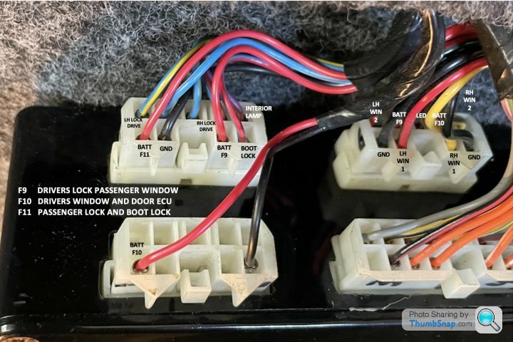
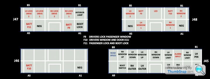
The door ECU is fed by three 12V supplies via fuses 9, 10 and 11.
F9 DRIVERS LOCK PASSENGER WINDOW (J47 A2 and J48 B4)
F10 DRIVERS WINDOW AND DOOR ECU
F11 PASSENGER LOCK AND BOOT LOCK
All switches (door releases, window up and down, interior lock) provide a momentary connection to earth (hence these inputs are shown in black on the diagram).
Window limit and door sensor switches also provide a connection to earth (I.e. when the window lowers enough to hit the limit switch and when the door is closed).
Interior lamps are switched on with a connection to earth (via the Door ECU when the doors are opened or via the switch on the lamp itself).
The door ECU locks and unlocks the car by watching for a ground signal from the alarm (on pin B3 of connector J45). This input is held high (12V) in locked mode, where the 3 external release buttons are ignored. When the alarm is disarmed, it provides a ground signal to the ECU which switches it to unlocked mode.
When arming the alarm the ECU responds by first closing windows and then providing a flashing signal to the green LED on the interior lock button (in front of shifter), of course it also ignores the external door and boot opening switches for the duration of the time the alarm is armed (internal switches will continue to open the doors, thank you Martin!). A fast blinking green light is an error signal from the ECU and is caused by an open boot/door, or other faults.
The microcontrollers are programmed with a timer for raising the windows, which activates once the window limit switch is open. This is why when the windows are down and you arm the alarm, the windows raise to the limit switch point and then pause for a second, before resuming their (timed) rise to a fully closed position.
The quality of the design and electronics is actually better than I expected.
I understand that the most common fault is failure of the relays, which can jam open (or closed).
The later ECU’s were populated with IP67 rated relays, so humidity/water ingress was less of an issue.
All components remain available, including the microcontrollers, which means that while these ECU’s have become rare, they are quite serviceable. TVR programmed the micro’s with certain parameters (which I am assuming are known to the TVR ECU repair specialists).
The ECU is generally quite reliable (provided it stays dry), especially if it has IP67 rated relays. But it is just the control element in a larger system of switches and actuators.
Actuators - three central locking servos are used to release the lock mechanisms for the doors and boot. These are often (incorrectly) called solenoids.
The ECU provides a continuous stream of 12V pulses (for as long as the door or boot buttons are pressed), to activate the servo. Unless the servo is weak/failing, only a single pulse should be required. New actuators are still available (for £15 each) but I have found them to have to a couple of issues:
1. Failure to retract - this is an issue in the door application. The lock mechanism needs the piston to retract (ever so slightly following a release operation), but some of these new servos simply do not retract enough. I do wonder if the Door ECU microcontroller can be reprogrammed to enable a reverse polarity pulse (as was seemingly originally intended)
2. High current draw - out of the 4 new units I bought, one was unable to retract the piston against the spring (used in the boot lock application), instead repeatedly blowing the 10A fuse
Door/boot release switches - there are 2 release switches per door (inner and outer) and a single outer release switch for the boot (under the badge). All 5 switches are wired (independently) back to the ECU and provide a connection to earth when pressed.
Window limit switches - a small micro-switch wired back to the ECU that provides a connection to earth when pressed. There is one in each door, activated by the window when it lowers about 5”.
Reed relays - magnetic switch wired back to the ECU, providing a connection to earth when not in close proximity to a magnet (door open). One is installed in each door and activated by a hidden magnet in the door jamb when the door is fully closed.
Testing
The ECU itself is probably the most robust part of the system. Weak points are:
1. Exterior door release switches (prone to water ingress)
2. Electrical multi-way connector in each door (water ingress)
3. Reed relay (at the bottom of each door) also prone to water ingress
4. Door lock actuators (wear-out over time)
5. Window channel felt wears out over time and slows the windows down
A lot of testing can be done with a simple multimeter at the Door ECU itself, which is very handy.
A meter with a continuity buzzer/tone is ideal, as it allows audible confirmation while testing switches in and around the car.
Always begin by checking for 12V on the five BATTERY pins that supply the ECU (fix one probe to earth and use the other probe to check each pin):
J46 - A5
J47 - A2 and A5
J48 - B2 and B4
If you don’t read 12V on any of these pins, then check the relevant fuses.
Door contacts - check the inputs at the ECU, for continuity to earth between LH PIN (J45 B1) or RH PIN (J45 A1), upon opening the door (thanks Marty). No continuity to earth with the door open should be followed by testing the door sensor with a magnet (with door open), if it still doesn’t result in continuity to ground, then it could be the connector in the door or the reed switch itself.
Door Release Switches - Check for continuity to earth (at the Door ECU) for each of the 4 door release inputs. If any switches fail to result in continuity to earth, then either the multi-way plug contacts in the door need cleaning OR the switch itself may be defective.
Window Switches - Check for continuity to earth (at the Door ECU) for each of the 4 window switches. If any switches fail to result in continuity to earth, then either clean up the pins on the plug behind the dash OR the switch itself may be defective.
Door actuators -
Assuming the door release switches have been tested and are working:
Unplug connector J47 to enable probing of the wiring going to the car, with the ECU disconnected. On the male J47 connector, check for resistance between B2 and B3 (driver’s door actuator) and B4 and B5 (passenger door actuator). You should read anywhere from a few ohms to 200 ohms.
- Open circuit means the actuator is either disconnected from the wiring loom, or damaged somehow.
- A dead short (continuity) means either a short in the loom or more likely a damaged actuator (F9 or F11 must also be blown).
- Check for 12V across the LOCK DRIVE 1 and LOCK DRIVE 2 outputs of the Door ECU when pressing the release button for that door. If you don’t have Mr Tickle arms, you can always probe the lock drive outputs while using a piece of wire to ground the correct door release input. For example, if checking for power to drivers door lock, then probe B2 and B3 on J47 and use a jumper to connect J45 A7 to earth (which is equivalent to pressing the drivers door switch under the mirror). If you don’t get 12V across the Door Lock output and fuse F9 and F11 are intact, then you may have a damaged relay.
After some further investigation (quite time consuming) I realised it was the new actuator that was the issue.
I thought it might be helpful if I did a write-up on what I learned (apologies in advance for any errors):
Cerbera electric door locks and windows are controlled by a box of tricks in the boot (on top of the fuel tank) - the Door & Window ECU.
The ECU comprises two 8-bit microcontrollers, 10 high current relays and a host of other electronics. The use of integrated resistor packs and transistor arrays means that there are surprisingly few discrete components. This improves reliability and longevity.
The ECU takes inputs from all switches and sensors associated with the windows and door/boot locks and provides power to the lock actuators and window motors.
6 relays are used to drive the lock actuators and the interior lamp. 1 each for the interior lamp and boot lock, but curiously, two for each door actuator. It would appear they designed the ECU to pulse the actuator once to push the arm out and then again but with reverse polarity to pull it back in. But in actual operation, no reverse polarity is applied and the accordion boot pulls the piston back a little, which proves sufficient. The boot lock actuator has a spring under the accordion-boot to ensure it always defaults back to full extension - this was apparently always intended as the ‘return position’ mechanism, as no reverse polarity relay exists.
4 additional 16 amp relays are used to drive the windows - 2 per window, 1 for up and 1 for down. Therefore, the window motor power is supplied by the ECU in the boot. The length of the wiring from the ECU to the window motors, plus the inevitable corrosion in the multi-way connector inside the door, mean that the motors probably never see a full 12V when ‘under load’ going up.
The two microcontrollers are the brain of the system, monitoring the inputs, managing the logical functions and driving the outputs. A pair of transistor array chips sit between the micro’s and the relays, to ensure adequate current drive.
Two PCB’s are used - a low power board (on top) is populated with the two microcontrollers, a couple of integrated resistor arrays and handful of power supply components. Power and ground are supplied to this board via J46 and all the sensor and switch inputs are connected via J45. The outputs from the micro’s are sent to a second (lower) PCB via a short 20-way ribbon cable.
The second PCB is populated with all the relays and the transistor arrays to drive them. All the drive signals are output via J47 and J48.
?
The door ECU is fed by three 12V supplies via fuses 9, 10 and 11.
F9 DRIVERS LOCK PASSENGER WINDOW (J47 A2 and J48 B4)
F10 DRIVERS WINDOW AND DOOR ECU
F11 PASSENGER LOCK AND BOOT LOCK
All switches (door releases, window up and down, interior lock) provide a momentary connection to earth (hence these inputs are shown in black on the diagram).
Window limit and door sensor switches also provide a connection to earth (I.e. when the window lowers enough to hit the limit switch and when the door is closed).
Interior lamps are switched on with a connection to earth (via the Door ECU when the doors are opened or via the switch on the lamp itself).
The door ECU locks and unlocks the car by watching for a ground signal from the alarm (on pin B3 of connector J45). This input is held high (12V) in locked mode, where the 3 external release buttons are ignored. When the alarm is disarmed, it provides a ground signal to the ECU which switches it to unlocked mode.
When arming the alarm the ECU responds by first closing windows and then providing a flashing signal to the green LED on the interior lock button (in front of shifter), of course it also ignores the external door and boot opening switches for the duration of the time the alarm is armed (internal switches will continue to open the doors, thank you Martin!). A fast blinking green light is an error signal from the ECU and is caused by an open boot/door, or other faults.
The microcontrollers are programmed with a timer for raising the windows, which activates once the window limit switch is open. This is why when the windows are down and you arm the alarm, the windows raise to the limit switch point and then pause for a second, before resuming their (timed) rise to a fully closed position.
The quality of the design and electronics is actually better than I expected.
I understand that the most common fault is failure of the relays, which can jam open (or closed).
The later ECU’s were populated with IP67 rated relays, so humidity/water ingress was less of an issue.
All components remain available, including the microcontrollers, which means that while these ECU’s have become rare, they are quite serviceable. TVR programmed the micro’s with certain parameters (which I am assuming are known to the TVR ECU repair specialists).
The ECU is generally quite reliable (provided it stays dry), especially if it has IP67 rated relays. But it is just the control element in a larger system of switches and actuators.
Actuators - three central locking servos are used to release the lock mechanisms for the doors and boot. These are often (incorrectly) called solenoids.
The ECU provides a continuous stream of 12V pulses (for as long as the door or boot buttons are pressed), to activate the servo. Unless the servo is weak/failing, only a single pulse should be required. New actuators are still available (for £15 each) but I have found them to have to a couple of issues:
1. Failure to retract - this is an issue in the door application. The lock mechanism needs the piston to retract (ever so slightly following a release operation), but some of these new servos simply do not retract enough. I do wonder if the Door ECU microcontroller can be reprogrammed to enable a reverse polarity pulse (as was seemingly originally intended)
2. High current draw - out of the 4 new units I bought, one was unable to retract the piston against the spring (used in the boot lock application), instead repeatedly blowing the 10A fuse
Door/boot release switches - there are 2 release switches per door (inner and outer) and a single outer release switch for the boot (under the badge). All 5 switches are wired (independently) back to the ECU and provide a connection to earth when pressed.
Window limit switches - a small micro-switch wired back to the ECU that provides a connection to earth when pressed. There is one in each door, activated by the window when it lowers about 5”.
Reed relays - magnetic switch wired back to the ECU, providing a connection to earth when not in close proximity to a magnet (door open). One is installed in each door and activated by a hidden magnet in the door jamb when the door is fully closed.
Testing
The ECU itself is probably the most robust part of the system. Weak points are:
1. Exterior door release switches (prone to water ingress)
2. Electrical multi-way connector in each door (water ingress)
3. Reed relay (at the bottom of each door) also prone to water ingress
4. Door lock actuators (wear-out over time)
5. Window channel felt wears out over time and slows the windows down
A lot of testing can be done with a simple multimeter at the Door ECU itself, which is very handy.
A meter with a continuity buzzer/tone is ideal, as it allows audible confirmation while testing switches in and around the car.
Always begin by checking for 12V on the five BATTERY pins that supply the ECU (fix one probe to earth and use the other probe to check each pin):
J46 - A5
J47 - A2 and A5
J48 - B2 and B4
If you don’t read 12V on any of these pins, then check the relevant fuses.
Door contacts - check the inputs at the ECU, for continuity to earth between LH PIN (J45 B1) or RH PIN (J45 A1), upon opening the door (thanks Marty). No continuity to earth with the door open should be followed by testing the door sensor with a magnet (with door open), if it still doesn’t result in continuity to ground, then it could be the connector in the door or the reed switch itself.
Door Release Switches - Check for continuity to earth (at the Door ECU) for each of the 4 door release inputs. If any switches fail to result in continuity to earth, then either the multi-way plug contacts in the door need cleaning OR the switch itself may be defective.
Window Switches - Check for continuity to earth (at the Door ECU) for each of the 4 window switches. If any switches fail to result in continuity to earth, then either clean up the pins on the plug behind the dash OR the switch itself may be defective.
Door actuators -
Assuming the door release switches have been tested and are working:
Unplug connector J47 to enable probing of the wiring going to the car, with the ECU disconnected. On the male J47 connector, check for resistance between B2 and B3 (driver’s door actuator) and B4 and B5 (passenger door actuator). You should read anywhere from a few ohms to 200 ohms.
- Open circuit means the actuator is either disconnected from the wiring loom, or damaged somehow.
- A dead short (continuity) means either a short in the loom or more likely a damaged actuator (F9 or F11 must also be blown).
- Check for 12V across the LOCK DRIVE 1 and LOCK DRIVE 2 outputs of the Door ECU when pressing the release button for that door. If you don’t have Mr Tickle arms, you can always probe the lock drive outputs while using a piece of wire to ground the correct door release input. For example, if checking for power to drivers door lock, then probe B2 and B3 on J47 and use a jumper to connect J45 A7 to earth (which is equivalent to pressing the drivers door switch under the mirror). If you don’t get 12V across the Door Lock output and fuse F9 and F11 are intact, then you may have a damaged relay.
Edited by Imran999 on Friday 24th February 16:07
Edited by Imran999 on Friday 24th February 16:11
Edited by Imran999 on Friday 3rd March 16:15
Edited by Imran999 on Friday 3rd March 16:20
Door Release Switches / Solenoids.
the early ones fitted by the factory and lots of replacements nowadays have too much play inside their "gearbox" and there is missing an internal reverse-spring.
this means after getting powered and opening the door the do not move-back enough to have a proper-stroke for the next opeing cycle.
only the proper (and expensive) Fiesta boot-release solenoids come with such a spring and they work.
all the aftermarket ones and even the early ones from the TVR factory not.
it looks like the later cars (tuscan, tamora, sagaris) were equipped with the fiesta boot-release solenoids (with its internal return-spring) even in the doors.
why? the standard-solenoids, over time, will get some play inside their operating-mechanism (sort of internal gearbox)...the rubber boot may return the rod away from latch, but during next opening cylce, the solenoid, as it still near to be fully extended, will not overcome the play and the door wont be unnlocked.
as consequence you try to unlock the door multiple times, the solenoid gets stressed, the door-opening ECU gets stessed and due to the constant stress on those items, the ECU may burn or break down.
Demondad said:
A very in depth post that must have taken a lot of time and knowledge of the subject. I think I'll definitely be referring to your test process sometime soon. My windows are sluggish. Thank you!
First point for sluggish windows is to clean the contacts in the plugs in the doorsImran999 said:
?
The door ECU is fed by three 12V supplies via fuses 9, 10 and 11.
F9 DRIVERS LOCK PASSENGER WINDOW (J47 A2 and J48 B4)
F10 DRIVERS WINDOW AND DOOR ECU
F11 PASSENGER LOCK AND BOOT LOCK
This is very useful and correct on my 99 but it not true for early Cerbs, both my 96 4.2 & 97 4.5 (98 registered) used:The door ECU is fed by three 12V supplies via fuses 9, 10 and 11.
F9 DRIVERS LOCK PASSENGER WINDOW (J47 A2 and J48 B4)
F10 DRIVERS WINDOW AND DOOR ECU
F11 PASSENGER LOCK AND BOOT LOCK
F7 DRIVERS LOCK AND BOOT LOCK
F13 PASSENGER LOCK (& starter)
(I didn't get as far as checking where the window supplies come from but they maybe different too, the 96 hand book says F10 for Right Window & F11 for Left Window, but it had the door locks power mixed up!)
The power for F13 comes from a different input to the fuse board, one that isn't used on the same fuse board from slightly later cars, so if your trying to swap bits from different year cars watch out!
Also the Speed 6 Cerbs & I think all late Cerbs use a totally different fuse board so they will most likely use different fuse numbers too....
Gassing Station | Cerbera | Top of Page | What's New | My Stuff